|
Author
|
Topic: Gemini: Identifying service module components
|
dfox
Member Posts: 208
From: Scarsdale, NY, United States
Registered: Mar 2010
|
 posted 05-11-2010 08:54 PM
   
I am trying to determine what the colored objects on the aft view of the Precise/Topping Gemini model represent.I have looked for a diagram of the service module that identifies these components. Can anyone direct me to such a diagram? Google Images has so far has not come through. Shayler's book "Steps To The Moon" did not have a diagram with this info either. |
golddog
Member Posts: 210
From: australia
Registered: Feb 2008
|
posted 05-12-2010 05:29 AM
I googled the image and whilst I'm not sure if I found the same image you saw, if it was then I believe what you are referring to represents the spherical storage bottles for oxygen, hydrogen and fuel. |
dfox
Member Posts: 208
From: Scarsdale, NY, United States
Registered: Mar 2010
|
posted 05-12-2010 02:30 PM
This shows the components that I am trying to identify. I assume they correlate to specific Gemini service module components. |
star51L
Member Posts: 354
From: Vilano Beach, FL, USA
Registered: Aug 2002
|
posted 05-12-2010 02:55 PM
Might these links help? |
dfox
Member Posts: 208
From: Scarsdale, NY, United States
Registered: Mar 2010
|
posted 05-12-2010 05:21 PM
Thanks, these diagrams are helpful although I have seen these already. I recall seeing a direct aft view somewhere I just can't find it! My guess so far is as follows: - "L" shaped blue object is a mount for communications and instrumentation equipment.
- The 2 adjacent Blue/Green spheres are for oxidizer (? oxygen).
- The lone blue/green sphere is cryogenic oxygen.
- The red spheres are fuel/propellant tanks.
- The black spheres are helium tanks.
Still unidentified are the blue object in the "9-o'clock" position and the 4 grey objects. |
mikej
Member Posts: 481
From: Germantown, WI USA
Registered: Jan 2004
|
posted 05-12-2010 06:31 PM
A screen capture from Spacecraft Films' Project Gemini Flight Controller Orientation DVD (highly recommended, BTW): 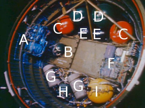 - ECS coolant pump
- ECS primary O2 supply
- OAMS fuel
- OAMS oxidizer
- Pressurant
- Electrical and electronic components
- Fuel cells
- Fuel cell cryogenic oxygen
- Fuel cell cryogenic hydrogen
|
dfox
Member Posts: 208
From: Scarsdale, NY, United States
Registered: Mar 2010
|
posted 05-13-2010 10:41 PM
Thanks that's AWESOME! Exactly what I needed. |
dfox
Member Posts: 208
From: Scarsdale, NY, United States
Registered: Mar 2010
|
posted 05-13-2010 10:50 PM
I just checked out that video. That's very cool. |
wheelchock
New Member Posts:
From:
Registered:
|
posted 06-27-2010 08:10 PM
I am looking for information on Gemini 10 aft service and re-entry modules. On some Gemini spacecraft, the aft modules (white painted) had longitudinal stiffeners running down the outside and they are visible in orbital photos. Some of the flights did not have these. Anyone know what the configuration of Gemini 10 was?Also, anyone have MacDac photos of these modules that would show the interior paint scheme. I am pretty sure the Revell kit's instruction to paint the inside zinc chromate green is in error. Editor's note: Threads merged. |
space1
Member Posts: 861
From: Danville, Ohio
Registered: Dec 2002
|
posted 06-27-2010 08:26 PM
The black stripes that appear to be stiffeners were painted. They were added to reduce the thermal radiance of the adapter because the coolant system was more effective than anticipated. Later missions (Gemini 8-12) replaced the stripes with patches of black Velcro for use as gripping areas during space walks. You can see the arrangement of these patches in this digital model.The interior of the adapter was covered in reflective silver-colored tape. ------------------
John Fongheiser
President
Historic Space Systems, http://www.space1.com |